Testing SyncE with Xena’s Advanced Timing Test Modules
Rev 1
Application Note
As carriers continue to adopt carrier Ethernet, new standards such as Synchronous Ethernet (SyncE) have been developed to enable high accuracy time synchronization of network devices and networks. The features of Xena’s Advanced Timing test modules (10 Gbps M2SFP+T and 1 Gbps M2SFPT) can be used to demonstrate network synchronization, and to perform go/no-go testing of SyncE networks.
Proving performance of SyncE Devices and Networks
As carriers continue to adopt carrier Ethernet, new standards such as Synchronous Ethernet (SyncE) have been developed to enable high accuracy time synchronization of network devices and networks. Without synchronization, Ethernet networks cannot deliver services that require high accuracy synchronization, such as mobile backhaul networks, where SyncE can be used to synchronize network devices between the cell site and switching office.
The features of Xena’s Advanced Timing test modules, the 1 Gbps M2SFPT and the 10 Gbps M2SFP+T, can be used to demonstrate network synchronization, and to perform go/no-go testing of SyncE networks. The audience for this application note is
• Network Equipment Manufacturers designing network elements supporting SyncE, for their customer training and proof of concept product demonstration.
• Carriers deploying Ethernet backhaul services, for operational personnel who verify network synchronization and for turn-up fault analysis.
With these Xena test modules, engineers can test SyncE using external and received clock source references, and measure the offset between the received frequency from the SyncE network under test and the external clock source reference, to verify proper frequency propagation throughout the SyncE network.
The Xena test modules provides a SMA input for an external clock reference, and provides the received Ethernet frequency via an SMA output connector. The test bed requires a 3rd party network time analyzer instrument for generating MTIE/TDEV graphs for frequency checking of Wander and Jitter of the SyncE network to the G.8262 standard.
The Xena test module performs MEF 10 Frame Delay Variation (FDV) measurements for analyzing Ethernet/IP jitter performance of the SyncE networks, and one-way or round-trip Ethernet/IP delay measurements. With the comprehensive Ethernet/IP traffic generation capabilities of the Xena test module, the user can also demonstrate that the accuracy of the time synchronization is independent of the Ethernet/IP traffic loading of the SyncE network.
Test bed
The test bed includes the following instruments and equipment:
• Clock reference generator (2.048MHz or 10MHz).
• Network time analyzer for MTIE/TDEV and frequency measurements.
• Xena test module M2SFPT (1 Gbps) or M2SFP+T (10 Gbps).
• The SyncE device(s) or network under test.
The front panel of the Xena test modules M2SFPT and M2SFP+T provides the following interfaces:
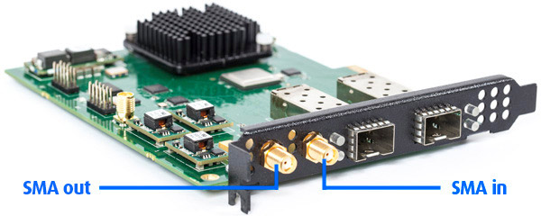
Figur 1 Xena M2SFPT and M2SFP+T test modules
The generic test bed setup is shown below in Figure 2. The red line represent frequency information, the dashed blue ones represent packet data.
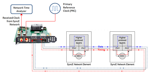
Figure 2 Test bed (generic)
The Xena test module receives its reference clock from the Primary Reference Clock (PRC) generator via the SMA input, and sends Ethernet/IP traffic into the SyncE network. At the receiving end (output of the SyncE network), the Xena card recovers the received line clock from Port 0, and makes it available on its SMA output, which is fed into the network timing analyzer. The network time analyzer performs frequency and MTIE/TDEV measurements, comparing the reference clock with the extracted clock and these results and graphs can then be used to document that the PRC clock is synchronously transferred across the SyncE network under test.
The technique used to compare the received output clock from the SyncE network to the Primary Reference Clock (PRC) is called Time Interval Error (TIE). The TIE measurements are the basis for the calculations of the Maximum Time Interval Error (MTIE) and Time Deviation (TDEV), which are industry-standard synchronization metrics. MTIE is the maximum time interval error (peak-to-peak) of the clock signal under test that occurs within a specified period of time compared to a PRC. MTIE is used for detecting important and very common clock signal frequency offsets. TDEV is a statistical value calculated from the measured TIE samples. Complementary to MTIE, it provides information about the frequency drift rate or the oscillator noise.
An example test bed is shown below in Figure 3, where the Network Time Analyzer is Timespy instrument (http://www.timefreq.com/page5652/Timespy.aspx), and the SyncE network under test is a wireless network. The Timespy can provide the PRC and also generate MTIE/TDEV graphs comparing the PRC with the received output clock from the synchronous wireless network. The output from the rear of the Timespy is a 10MHz PRC, and the input on the front of the Timespy is connected to the received clock frequency. The XenaManager GUI is used to generate different Ethernet/IP traffic load patterns, and performing MEF 10 Frame Delay variation (FDV) and Latency measurements across the SyncE network.
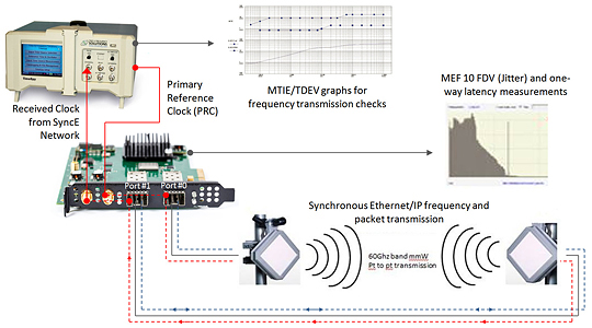
Figure 3 Example Testbed for wireless network
How to setup the Xena Test Module
The timing features of the M2SFPt and M2SFP+T test modules are selected on the test module properties tab in the XenaManager GUI application:
1) Select the SMA input as a 10MHz reference clock signal.
2) Select the SMA output as the recovered clock from port 1.
3) Select the Tx clock source as the SMA input.
4) Select the Tx and SMA output clock filter to the maximum value (7019 Hz), to pass jitter/wander transparent from the SMA input to port 0 and 1 transmit data.
Figure 4 Test module settings in XenaManager